
Overview
The purpose of the vacuum suitcase project was to devise a method for transferring samples under vacuum between thin-film growth, device fabrication, and characterization/measurement.
I undertook the vacuum suitcase project as an undergraduate research fellow in Dr. Kenneth Burch's LASE lab. The project lasted from 2018 to 2019 and was the subject of my senior thesis.
A vacuum suitcase is a piece of equipment that is responsible for transferring a sample under vacuum. Vacuum suitcases are not uncommon in scanning tunneling microscopy research (STM), but are very uncommon in magnetotransport research, which was the area of research I was in in the Burch Lab. In fact, the Burch Lab suitcase is unique in its capabilities to my knowledge.
More information on the project can be found in each of the below sections.
Vacuum Suitcase
Motivation
In the course of the research that is conducted in LASE, it is often desirable to transfer samples of extremely high quality without degradation between different vacuum systems.
LASE is a condensed matter physics lab focusing on studying exotic phases of matter. In order to conduct this research, samples of the utmost quality must be used. To maintain their quality, samples cannot see air. This is because samples may lose their interesting phases of matter, such as iron selenide losing its superconducting property once oxidized, or because particulate matter can disrupt the sensitive interfaces which are the unique location at which some of these phenomena occur.
LASE has an inert argon glovebox in which characterization and device fabrication takes place; however, the samples must be removed and exposed to air in order to transfer into measurement systems. Standard practice in the area of magnetotransport research is to "cap" the device with hBN to protect it from the environment; however, it has been shown that this extra layer can affect the electronic properties of the device, as has been shown in tungsten diselenide. Therefore, some doubt can be cast on results that are obtained from capped samples.
The vacuum suitcase project was created in order to address these challenges. The goal was to create an intermediary piece of equipment that will allow lab scientists to transfer samples under vacuum between systems so that a sample is in either in an inert argon environment or under vacuum for the entirety of its existence.
The addition of the vacuum suitcase to the lab will allow for access to exciting domains of study that are uniquely accessible to LASE. Among these domains are:
In order to take the concept of a vacuum suitcase beyond the common STM use and design it to be used with a magnet, cryo-optical system, MBE, STM, and argon glovebox fabrication facility, I faced many design challenges. The design approach I used was iterative improvement while making sure to stay within the necessary design parameters. Some of these parameters are:
-
Compatibility with
-
Need for intralaboratory universal sample holder
Below we see how these design parameters influenced the design process
A h-BN capped sample
Tungesten Diselenide Crystal Structure
-
Accommodation of collaborators' sample holders
-
UHV capability (<1e-8 mBar)
-
Spatial constraints
-
Thermal requirements
-
Magnetic requirements
-
Geometric constraints
-
Use with argon, air, vacuum
-
Cost
Basic Operation
The basic operation of a vacuum suitcase involves a sample space under constant vacuum and an intermediate chamber which is vacuumed and vented during operation.
The basic operation of a vacuum suitcase is quite simple. The process for transfer into a vacuumed system is found below with an accompanying slideshow for visualization:
1. The system, e.g. magnet (orange), starts out under vacuum, separated from the environment by a valve (blue)
2. The suitcase is attached to the system. The suitcase is composed of two compartments: (i) a sample space (green) that is constantly under vacuum in which the sample sits, separated from (ii) a transfer tee (red) by a valve. The transfer tee is under atmospheric pressure at this point from being connected to the magnet.
3. With both valves closed, the transfer tee is then vacuumed out so that all chambers now sit at ~1e-8 mBar
4. With all chambers under the same pressure, the valves can now be opened and the sample passed through to the magnet. In this way, the sample is always under vacuum and therefore not destroyed by environmental contaminants.


Modeling & Design
In order to ensure that all aspects of my design were copacetic and the transfer process would go as intended, I created a 3D model of the lab.
Although the above theoretical operation is quite straightforward, the practical implementation of such a system requires careful design. This is especially true for this project since the LASE suitcase needs to be compatible with a variety of systems that were designed independently by different companies. Some questions that needed answering to translate the above procedure from theory to practice are:
How is the sample to be held in the suitcase sample space?
How is the sample to be moved under vacuum?
How is the suitcase to handle different sample holder types?
What materials are compatible with all pieces of equipment?
How is proper alignment during transfer to be ensured?
To address these questions and many more, I created a 3D model of the laboratory. The model allowed me to test various design ideas I had in order to compare them on ease of transfer, cost, practicality, machinability of custom parts, ease of future upgrade implementation, etc. The model also allowed for visualization of the entire transfer process, start to finish. Visualization for a system as complicated as this is very important in order to make sure no small detail is overlooked, such as an inability to access tight areas with a wrench, or an inability to fit all necessary valves in a small space.
Below is a streamlined version of the design process with accompanying design choice logic
Zeljkovic Lab Suitcase
The Zeljkovic Lab, a collaborating lab of LASE, already had a suitcase for transfer between its MBE and STM, so my first task was to ensure that this suitcase could transfer into LASE's argon fabrication chamber. This enables exfoliation onto thin films and 2D material monolayer STM. Because of the UHV requirements for their systems (~1e-11 mBar), the addition of an intermediate chamber to the transfer process was required.
The process for transfer into the LASE argon fabrication chamber is found below with an accompanying slideshow for visualization:
1. The glovebox (orange), is separated from the vacuumed intermediate chamber (purple) by a valve. The suitcase is attached to the intermediate chamber, with its sample space (green) under vacuum and its transfer tee (red) full of air from attaching the suitcase.
2. The intermediate chamber is vacuumed out.
3. Two of the valves are opened and the sample is moved into the intermediate chamber.
4. The valves are closed and the intermediate chamber flooded with argon.
5. The remaining valve is opened and the sample transferred into the fabrication chamber.
In the last slide is the model of the Zeljkovic suitcase attached to the intermediate chamber/glovebox.

The Zeljkovic Lab STM uses a Unisoku style holder, modeled below. Since the intermediate chamber needs to hold the sample temporarily while the chamber is vented, I designed a block to receive the sample holder, seen below. Note that this was the only custom component manufactured in-house that was not machined by me.
Unisoku Sample Holder

Unisoku Sample Holder Receiver

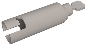
New Sample Holder
In addition to the Unisoku holder, the transfer process required accommodation of the new intralaboratory LASE sample holder that was designed as part of this process. The sample holder was designed by a third party company - Montana Instruments. I worked closely with the engineers to ensure that the design stayed within the project parameters, suggesting features and catching design flaws during the design process. A slideshow can be seen below with some of the early design iterations.

The final sample holder design can be seen in the below slideshow along with its receiver

Sample Area
Contacts
Dovetail
Lead Screw
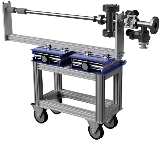
This sample holder is held onto a manipulator with rotational and linear degrees of freedom by a head as seen below

Manipulator
Sample Space
Valve
Lab Jacks
Height & pitch adjustment
Roll adjustment
Wheels
Lateral adjustment
Port Aligner
Yaw adjustment
Transfer Tee
The manipulator is then mounted along with some vacuum components onto a cart which is used for both transportation and alignment.
The suitcase can then be moved between equipment to transfer samples between fabrication and measurement under vacuum
Vacuum suitcase attached to glovebox intermediate chamber


Measurement of air-sensitive samples
(e.g. CGT, RuCl3, FeTeSe)
Raman data showing the air-sensitivity of CGT
Tian, Yao et al. 2D Materials, 2016, Vol.3(2), p.025035 (9pp)
Hover for more infomration
Logistics
I handled all logistical aspects of the project, working to cut the cost of the project significantly and create a timeline for the project organized in a Gantt chart.
Beyond the technical aspects of the vacuum suitcase project, I was also responsible for the logistical side of the project. I worked to create a comprehensive parts list and negotiate with various suppliers to cut costs. In addition, I created a timeline of the project in the form of a Gantt chart for organization and communication with other teams in the lab. Some parts of the Gantt chart can be found below for reference.

Machining & Assembly
I machined all custom components but one that I had designed, done in part by teaching myself how to use the CNC capabilities of a mill in the department shop.
After the design and ordering stages of the project, I prepared for assembly by machining all of the custom components (except one) in the design. I shadowed under the head machinist, Paul Dee, in the department shop for several weeks to expand my previously basic machining knowledge. Eventually I was trusted to work without supervision and was the only person allowed to use the CNC mill besides the head machinist himself. I also taught myself how to use the more complicated .DXF path processing capabilities of the CNC since the head machinist was not familiar with these features.
Some pictures from my time machining are below:
Basic Components

Sample Holder Receiver Dovetail

OFHC Copper Thermal Contact
Sample Holder Receiver Dovetail

Sample Holder Receiver Assembly
OFHC Copper Thermal Contact

Suitcase / Chamber Assembly
Testing & Optimization
Once the assembly of the suitcase and related systems had been completed, I tested all components and created an optimized transfer procedure.
After the machining and assembly, I tested and optimized the transfer procedure to ensure the repeatable transfer of samples while maximizing throughput.


Future Directions
During design, I made sure to future-proof the system by designing for the accomadation of additional capabilities that would improve system performance.
Capability and cost were two factors that were at odds during the design phase of the project. A balance between the two was struck in order to yield the design with the most impact for the lowest cost; however, should the need to upgrade the system arise in the future, I designed the suitcase to be immediately ready for several upgrades. Some examples of such possible future modifications are below.
Sample Holder Adapter
The Burch and Zeljkovic suitcases are compatible only with their own sample holders. Transfer from one to the other happens during fabrication. In order to overcome this obstacle, I designed an adapter for the Burch Lab suitcase to accept Unisoku holders. The idea was originally conceived by He Zhao of the Zeljkovic Lab.
Vacuum Improvements
The LASE suitcase is not actively pumped in transit. This is because the vacuum degradation rate in the sample space is low enough that the suitcase can be moved from system to system while keeping the sample space below 1e-6 mBar of pressure. Should there be a need to actively pump in the future, I designed the suitcase to be able to incorporate ion and getter pumps on the sample space without modification.
The transfer tee of the LASE suitcase is also currently flushed with air when attaching/detaching the suitcase. To improve vacuum, the transfer tee may be attached to a nitrogen tank for flushing. This would allow for lower base pressure and greater time between bakeouts.
Nitrogen Flushing
Ion/Getter Ports
Manual
In order to ensure that the system could be properly maintained and troubleshot in my absence, I wrote a system manual for future scientists in the lab.
I found that organization was very important for this project due to its size; so, in addition to building the suitcase itself, I also wrote a manual for it. The manual, with accompanying Google Drive folder, is for future lab scientists and provides a comprehensive breakdown of the project. The manual and folder give details on every part of the project, including
-
Motivation and Overview ( for new scientists to get oriented )
-
Transfer procedures and limiting factors ( for scientists who wish to use the suitcase for their research )
-
CNC files, 3D files, and shop drawings ( in case a custom part breaks or more sample holders are needed )
-
Design process information ( explanation for design choices in case modification is desired )
-
Quotes and parts lists ( for replacement parts )
and more. A redacted version of the suitcase manual can be downloaded below